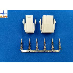
4.20mm Pitch Board To Wire Connectors , Crimp Style Connectors C4255M-T
1, The specification of the product including basic size information, electrical and mechanical properties.
| Basic size information |
| Termination Interface Style | crimp or compression |
| Processing methods | E-stamping before tin-plated |
| Insulation O.D. | 3.10mm(Max) |
| Part No. | C4255M-TPE or C4255M-TPE-H or C4255M-TPE-TH |
| Application | signal |
| |
| Electrical properties |
| Current Rating | 9A AC, DC |
| Voltage Rating | 600V AC, DC |
| Contact Resistance | 10mΩ Max |
| Insulation Resistance | 1000mΩ min |
| Withstanding Voltage | 1500V AC/minute |
| |
| Mechanical properties |
| Temperature range | -25℃ to 85 ℃ |
| Other information please kindly check the following picture. |
2, Related drawing and report
The following pictures are engineering drawing and testing report for your reference, wish these can help you to purchase the ideal and right parts from us. Thank you!

| 1. Scope This specification covers the requirements for product performance of 4.20mm pitch wire to board & wire to wire connectors series. 2. Construction,Dimensions,Material & Plating See the attached drawings 3. Ratings & Applicable Wires | Item | Standard | | Rated Voltage (Max.) | 600V AC/DC | Insulation O.D. 3.10mm (Max.) | | Rated Current (Max.) And Applicable Wires | AWG#14 | 6A AC/DC | | AWG#16 | | AWG#18 | | AWG#20 | 5A AC/DC | | AWG#22 | 4A AC/DC | | AWG#24 | 3A AC/DC | | Ambient Temperature Range | -25℃ ~ +85℃* | *: Including terminal temperature rise 4. Electrical Performance | Test Description | Procedure | Requirement | | 4-1 | Contact Resistance | Mate connectors, measure by dry circuit, 20mV max., 10mA.(Based upon JIS C5402 5.4) | 10mΩ (Max.) | | 4-2 | Insulation Resistance | Mate connectors, apply 500V DC between adjacent terminal or ground. (Based upon JIS C5402 5.2/MIL-STD-202 Method 302 Cond. B) | 1000MΩ (Min.) | | 4-3 | Dielectric Withstanding Voltage | Mate connectors, apply 1500V AC (rms) for 1 minute between adjacent terminal or ground. (Based upon JIS C5402 5.1/MIL-STD-202 Method 301) | No Breakdown. | | 4-4 | Contact Resistance on Crimped Portion | Crimp the applicable wire on to the terminal, measure by dry circuit, 20mV (Max.), 10mA. | 5mΩ (Max.) | 5. Mechanical Performance | Test Description | Procedure | Requirement | | 5-1 | Actuator Insertion & Withdrawal Force | Insert and withdraw connectors at the speed rate of 25±3mm / minute. | Refer to paragraph 7 | | 5-2 | Crimping Pull Out Force | Fix the crimped terminal, apply axial pull out force on the wire at the speed rat of 25±3mm / minute.(Based upon JIS C5402 6.8) | AWG#14 | 11.0kgf (Min) | | AWG#16 | 10.0kgf (Min) | | AWG#18 | 9.0kgf (Min) | | AWG#20 | 6.0kgf (Min) | | AWG#22 | 4.0kgf (Min) | | AWG#24 | 3.0kgf (Min) | | 5-3 | Terminal Insertion Force. | Insert the crimped terminal into the housing. | 1.50kgf (Max.) | | 5-4 | Terminal/Housing Retention Force. | Apply axial pull out force at the speed rate of 25±3mm / minute on the terminal assembled in the housing. | 3.00kgf (Min.) | | 5-5 | Pin Retention Force | Apply axial push force at the speed rate of 25±3mm / minute | 3.00kgf (Min.) | | 5-6 | Latch Yield Strength | Mate connectors and pull apart until both latches break at the speed rate of 25±3mm / minute | 7.0kgf (Min.) | | 5-7 | Panel Mount Retention Force | Insert the housing into panel cut out, push housing opposite the way it was assembled until the locking barbs break at the speed rate of 25±3mm / minute. | 16.0kgf (Min.) | | 5-8 | Durability | When mated up to 50 cycles repeatedly by the rate of 10 cycle per minute. | Contact Resistance 20mΩ (Max.) | | 5-9 | Vibration | Amplitude: 1.5mm P-P Sweep time: 10-55-10 Hz in 1 minute Duration: 2 hours in each X.Y.Z. axes. (Based upon MIL-STD-202 Method 201A) | Appearance No Damage. Contact Resistance 20mΩ (Max.) Discontinuity 1 μsec.(Max.) | | 5-10 | Physical Shock | 490m/s²{50G},3 strokes in each X.Y.Z. axes. (Based upon JISC0041/MIL-STD-202 Method 213B Cond. A) | |
| 6. Environmental Performance And Others | Test Description | Procedure | Requirement | | 6-1 | Temperature Rise | Carrying rated current load.(Based upon UL 498) | 30℃(Max.) | | 6-2 | Heat Resistance | 85±2℃,96 hours (Based upon JIS C0021/MIL-STD-202 Method 108A Cond. A) | Appearance No Damage. Contact Resistance 20mΩ (Max.) | | 6-3 | Cold Resistance | -25±3℃,96 hours (Based upon JIS C0020) | | 6-4 | Humidity | Temperature: 40±2℃ Relative Humidity : 90~95% Duration: 96 hours (Based upon JIS C0022/MIL-STD-202 Method 103B Cond. B) | Appearance No Damage. Contact Resistance 20mΩ (Max.) Insulation Resistance 100MΩ (Min.) Dielectric Withstanding Voltage Must meet 4-3 | | 6-5 | Temperature Cycling | 5 cycles of: a) -55℃ 30 minutes b) +85℃ 30 minutes (Based upon JIS C0025) | Appearance No Damage. Contact Resistance 20mΩ (Max.) | | 6-6 | Salt Spray | Tin-plated 12 hours / Gold- plated 24 hours exposure to a salt spray from the 5±1% solution at 35±2℃. (Based upon JIS C0023/MIL-STD-202 Method 101D Cond. B) | | 6-7 | SO2 Gas | 24 hours exposure to 50±5ppm. SO2 gas at 40±2℃. | | 6-8 | NH3 Gas | 40 minutes exposure to NH3 gas evaporating from 28% Ammonia solution. | | 6-9 | Solderability | Soldering Time: 5±0.5 sec. Solder Temperature: 245±5℃ | Solder Wetting 95% of immersed area must show no voids, pin holes | | 6-10 | Resistance to Soldering Heat | Solder pot method Soldering time: 10±0.5 sec. Solder Temperature: 260±5℃ Solder iron method Soldering Time: 5±0.5 sec. Solder Temperature: 370℃ ~ 400℃ | Appearance No Damage. | 7. Actuator Insertion/Withdrawal Force [Unit : kgf] | Circuits | At Initial | Circuits | At Initial | | Insertion (Max.) | Withdrawal (Min.) | Insertion (Max.) | Withdrawal (Min.) | | Single | 0.70 | 0.20 | 10 | 7.00 | 2.80 | | 02 | 1.40 | 0.50 | 11 | 7.70 | 3.05 | | 03 | 2.10 | 0.75 | 12 | 8.40 | 3.30 | | 04 | 2.80 | 1.10 | 14 | 9.80 | 3.90 | | 05 | 3.50 | 1.35 | 16 | 11.20 | 4.40 | | 06 | 4.20 | 1.60 | 18 | 12.60 | 5.00 | | 07 | 4.90 | 1.90 | 20 | 14.00 | 5.60 | | 08 | 5.60 | 2.20 | 22 | 15.40 | 6.10 | | 09 | 6.30 | 2.50 | 24 | 16.80 | 6.70 | |
3, FAQ
Q:Do you allow multiple design per setup?
A:Yes.We accept OEM/ODM service and allow multiple design per setup.
Q:How long does shipping take?
A:It depends on the destination location and quantity. In most developed country, delivery by Fed x/UPS/DHL is normally 2-3 days(excluding weekends).
Q: How is the goods packaged ?
A: Usually in PE bads, tube, pipe and with outside carton box.
4, we can offer multiple, safe and fast shippment for you!
We have very good cooperation with world famouse delivery company, and the can offer us good service and favorable price. It's sure that every business between us will be fast and happy. Choose us! Let's connect the realistic and electronic world.