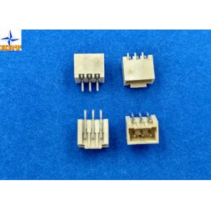
Wafer Connector Pitch 1.50mm Pin Brass/ Tin-plated wire to board connectors
Description:
1.A1501 series Wafer have A1501WV A1501WR (Single row housing suitable A11501-T series terminal )
2, Wafer used materials:PA6T , Fire-protection rating is UL 94-V0. Minimum packing quantity is 1000pcs/bag.
3. Single row Wafer we have 02PIN~15PIN ,The daily production capacity is 30 to 50 KPCS.
4.Terminals are stamped by Phosphor Bronze, E-Stamping beforeTin-plated , Tin-plated we calling A1501-TPe , Minimum packing quantity is 20,000pcs/Reel. The daily production capacity is 300 to 400 KPCS.
5.Terminals' wire range :AWG #22--#28insulation OD is0.90mm(Max).
| Test Description |
Procedure |
Requirement |
|
Contact Resistance
|
Mate connectors, measure by dry circuit, 20mV max., 10mA.(Based upon JIS C5402 5.4) |
20mΩ (Max.) |
| Insulation Resistance |
Mate connectors, apply 500V DC between adjacent terminal or ground. (Based upon JIS C5402 5.2/MIL-STD-202 Method 302 Cond. B) |
1000MΩ (Min.) |
| Dielectric Withstanding Voltage |
Mate connectors, apply 800V AC (rms) for 1 minute between adjacent terminal or ground. (Based upon JIS C5402 5.1/MIL-STD-202 Method 301)) |
No Breakdown. |
| Contact Resistance on Crimped Portion |
Crimp the applicable wire on to the terminal, measure by dry circuit, 20mV (Max.)., 10mA. |
5mΩ (Max.) |
| Current rated |
3A AC/DC maximum |
| Voltage rated |
350V AC/DC |
| Withstand voltage |
500V AC/minute |
| Insulation resistance |
1000MΩ min |
| Contact resistance |
20MΩ max |
| Operating temperature |
-25 - 85°C |

Environmental Performance And Others
| Test Description |
Procedure |
Requirement |
| 6-1 |
Temperature Rise |
Carrying rated current load.(Based upon UL 498) |
30℃(Max.) |
| 6-2 |
Heat Resistance |
85±2℃,96 hours (Based upon JIS C0021/MIL-STD-202 Method 108A Cond. A) |
Appearance No Damage.
Contact Resistance 40mΩ (Max.)
|
| 6-3 |
Cold Resistance |
-25±3℃,96 hours (Based upon JIS C0020) |
| 6-4 |
Humidity |
Temperature: 40±2℃
Relative Humidity : 90~95%
Duration: 96 hours
(Based upon JIS C0022/MIL-STD-202 Method 103B Cond. B)
|
Appearance No Damage.
Contact Resistance 40mΩ (Max.)
Insulation Resistance 100MΩ (Min.)
Dielectric Withstanding Voltage Must meet 4-3
|
| 6-5 |
Temperature Cycling |
5 cycles of:
a) -55℃ 30 minutes
b) +85℃ 30 minutes
(Based upon JIS C0025)
|
Appearance No Damage.
Contact Resistance 40mΩ (Max.)
|
| 6-6 |
Salt Spray |
Tin-plated 12 hours / Gold- plated 24 hours exposure to a salt spray from the 5±1% solution at 35±2℃. (Based upon JIS C0023/MIL-STD-202 Method 101C Cond. B) |
| 6-7 |
SO2 Gas |
24 hours exposure to 50±5ppm.
SO2 gas at 40±2℃.
|
| 6-8 |
NH3 Gas |
40 minutes exposure to NH3 gas evaporating from 28% Ammonia solution. |
| 6-9 |
Solderability |
Soldering Time: 5±0.5 sec.
Solder Temperature: 245±5℃
|
Solder Wetting 95% of immersed area must show no voids, pin holes |
| 6-10 |
Resistance to Soldering Heat |
Solder pot method
Soldering time: 10±0.5 sec.
Solder Temperature: 260±5℃
Solder iron method
Soldering Time: 5±0.5 sec.
Solder Temperature: 370℃ ~ 400℃
|
Appearance No Damage. |
Actuator Insertion/Withdrawal Force
[Unit : kgf]
| Circuits |
At Initial |
| Insertion (Max.) |
Withdrawal (Min.) |
| Single |
0.70 |
0.06 |
| 02 |
2.50 |
0.30 |
| 03 |
3.00 |
0.40 |
| 04 |
3.50 |
0.50 |
| 05 |
4.00 |
0.60 |
| 06 |
4.50 |
0.70 |
| 07 |
5.00 |
0.80 |
| 08 |
5.50 |
0.90 |
| 09 |
5.50 |
1.00 |
| 10 |
6.00 |
1.10 |
| 11 |
6.00 |
1.20 |
| 12 |
6.50 |
1.30 |
| 13 |
6.50 |
1.40 |
| 14 |
7.00 |
1.50 |
| 15 |
7.00 |
1.60 |